Freelance research, design, repair and reverse engineering of electronic, mechanical and optical systems.
Based in Preston, Lancashire in the United Kingdom.

Audio electronics repair

1BitHigh repairs, or upgrades, a wide variety of high end audio equipment.

• Audio Power Amplifiers - particularly the Cambridge Audio A75 / A250 Monoblocks, MF A370 & MF P270, Toshiba / Aurex SC-M15
• CD players - particularly the Cambridge Audio CD1 analogue section
• Pre amplifiers - particularly the Toshiba / Aurex SY-C15
• Digital to Analogue converters (DACs) - particularly the Musical Fidelity Digilog
• Analogue to Digital converters (ADCs)

Case study - Musical Fidelity A370 rebuild

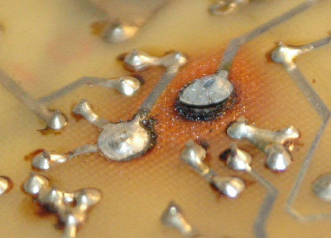
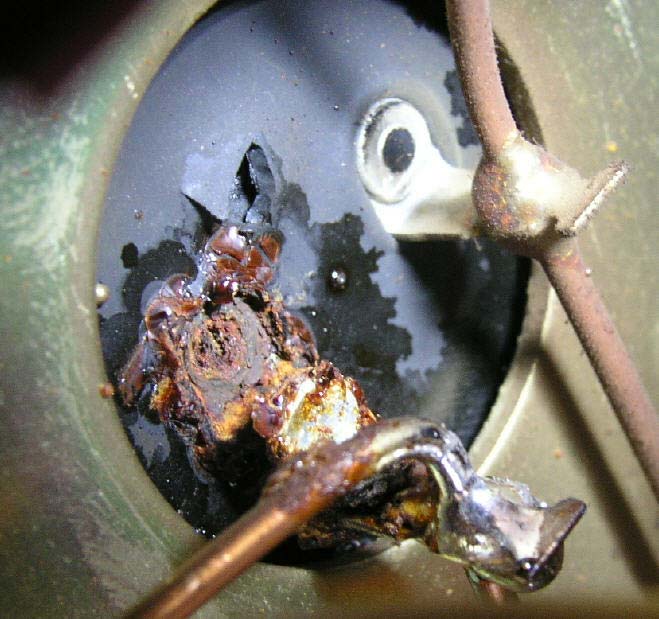
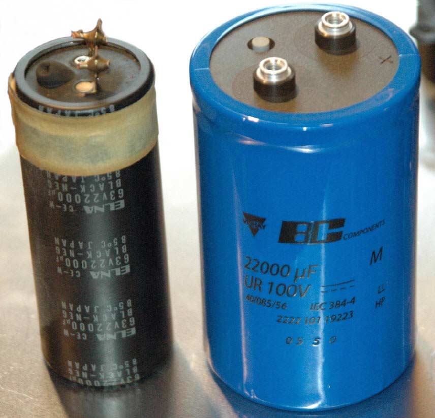
The Musical Fidelity A370 was one of the best loved power amplifiers of British origin. It's smooth effortless power delivery made listening to music a real pleasure. Given the operating temperature and some of its design it's a wonder that these have kept going as long as they have. Many have suffered from thermal damage and its associated effects. The main electrolytic power supply capacitors often dry out, some of the solder joints fatigue and go dry. The output devices tend to loosen up over time. That said it's a wonder these continue to sound as good as they do, even in a poor state. A complete overhaul is recommended before a fault occurs that causes a lot of damage, especially as the original output devices now are in short supply.

Initial state

Musical Fidelity A370 heat damaged printed circuit board
A370 burned PCB
An original electrolytic capacitor from the Musical Fidelity A370 that has vented
A370 leaking capacitor
With this particular amplifier, the customer mentioned that was running significantly cooler on one side than it had been doing, with some deterioration in the audio. Whilst a warm up period for best sound is to be expected it sounded unexpectedly 'harsh' and 'brittle' for its first several hours of use, after which it would settle down. Removing the lid revealed a spread of problems. Several power supply electrolytic capacitors had vented and due to corrosion one was not in-circuit anymore. Areas of burning to the circuit boards and one of the larger power resistors had lifted its tracking from the circuit board but remarkably hadn't broken the copper tracking. Further investigation showed one variable resistor had failed, some of the ceramic capacitors had cracked and one output device was suspect. The soft start circuit didn't function properly, indeed was debatable whether it'd ever functioned at all due its design. Dry joints were into double figures and one of the input leads was actually cracked. The lamp in the power-on switch had also failed.

Due to the likelihood of a serious failure pushing the amplifier beyond repair it was decided to completely rebuild it.

Rebuilding

An A370 old electrolytic capacitor vs the replacement
Old vs new
An interest in quality music reproduction spanning many years and the electronic design behind it made this rebuild project very interesting. A lot of knowledge and experience, which any designer of such equipment will know can be hard to quantify, was brought to bear. One of the key problems was that the original 22,000uF 50V capacitors were underrated for the 68V supply rails. So any modern replacement was going to be physically bigger and render the original capacitor racks obsolete. MF claimed the particular brand they used could take it. Maybe they could, but I wasn't happy with this, especially given the higher operating temperatures. The next capacitor voltage up (80 Volt working) wasn't immediately available and the next one up again, 100V, were much bigger than the originals. However given the operating conditions the excess working voltage could be usefully transposed into extended working life. The amplifier internals were completely reorganised, changing the mounting positions of the toroidal transformers and the capacitor racks to bring the power supply into more intimate contact with the output stage and also better divide up the amplifier internals thermally. The capacitors were mounted to a new central chassis and boards of their own. The physics of it meant that more of chimney was formed internally to both deal with the heat produced and also partially shield the capacitors from it. All polarised capacitors were replaced with equivalent or higher specification parts, the high frequency bypassing was improved, several small signal transistors were replaced. Some of the pcb tracking was bypassed with a high quality wire. A couple of resistors were re-engineered to aid support and bring surface temperatures down. The boards were defluxed and chemically washed. A.C. rectification went from a 2 rectifier design to 4. The bottom of the case gained new venting holes placed to address heat issues. The top lid mounting was modified to produce a small peripheral vent to compliment the work done on the floor of the case. The soft start circuit was completely re-designed as the original was prone to oscillation during power up due to its design. The new physical setup also allowed us to run the amplifier up to temperature and easily set its biasing up in a now very full case.

The results

A view into the top of the Musical Fidelity A370-2 after rebuild
A370-2 rebuilt
It was immediately noticeable that the initial brittle nature of the sound had gone and the amplifier had a renewed command of the audio stage. The very bottom end initially lacked depth but this isn't unusual when listening to rebuilt power supplies. During the burn-in period this gradually extends and ultimately disappears. Even from cold this now sounded much better than it had after it'd been on for several hours before. The sibilance to vocals had disappeared and the sound stage was generally more clean and open. It was a great delight to hear the monster go through its paces again.

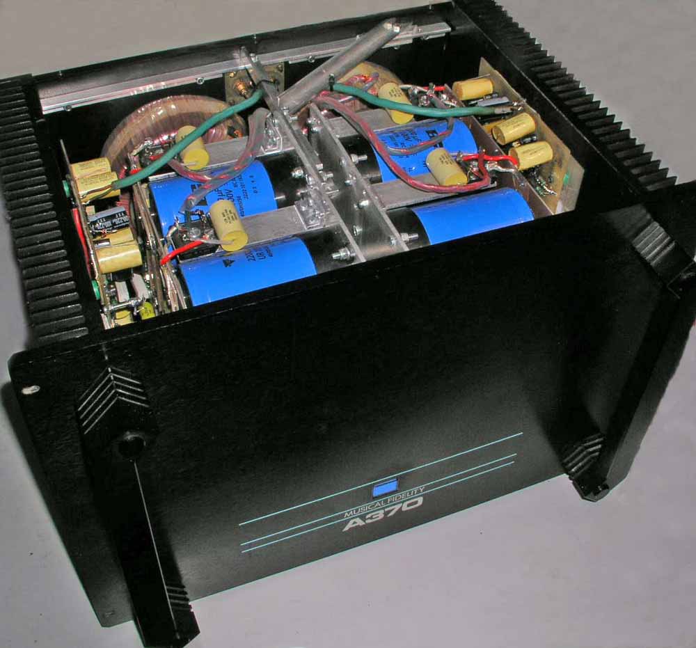
The new soft start circuit markedly reduced the inrush current. The soft start was now voltage dependant and the new sequence had a proper response in the case of mains supply brown outs. Previously this amplifier would not survive being run with anything less than a 10A fuse in the plug. Now the initial inrush was limited to 5A peak whilst the capacitor bank acquired about 1/2 of its charge. The blown incandescent lamp in the power on switch was replaced with its modern solid state equivalent. In all, an already heavy amplifier gained just under 7Kg in weight. Even though the case was much more tightly packed, thermally the amplifier was happier.

Testing of it from an electronics point of view for frequency response, phase response / correct phase and stability into complex loads completed its testing.

Side note: A couple of people have pointed out that the front of this amplifier isn't marked as a Mk2. It was a Mk2 inside. There seems to be quite a few variants of these about. Different markings, different boards in them and different capacitor racks.

For rebuild, modification or upgrade of a much loved piece of HiFi equipment please do get in touch.